






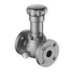
Sampling Coolers and Heat Exchangers for High-Temperature Sampling
Many refining, petrochemical, and power streams are far too hot to sample directly. A sampling cooler — a small heat exchanger dedicated to sample conditioning — brings the fluid down to a temperature the analyzer or laboratory can handle, while protecting seals, tubing, and instrumentation from thermal damage. Done well, it also prevents the sample from flashing or condensing, which is what keeps the sample representative.
This guide covers why high-temperature samples need conditioning, the main cooler designs, how to size them, and the material and dew-point considerations that determine whether the cooled sample still means what it is supposed to mean.
Why High-Temperature Samples Need Conditioning
A sample drawn at 200–350°C cannot go straight to an analyzer. The problems are both practical and analytical:
- Instrument and seal limits — analyzers, valve seals, and tubing have maximum service temperatures well below high-temperature process conditions.
- Flashing and two-phase flow — a hot, pressurized liquid will flash to vapor as it cools and depressurizes, giving a two-phase stream that no single-phase measurement can interpret.
- Safety — hot sample lines are an operator burn hazard and a source of thermal stress on fittings.
- Representativeness — uncontrolled cooling can condense heavy components and lose light ends, so the analyzed sample no longer matches the process.
A properly sized sampling cooler addresses all four by bringing the sample to a controlled, single-phase (or dew-point-managed) condition before it reaches the analyzer.
Sampling Cooler Designs
| Design | Construction | Best For |
|---|---|---|
| Shell-and-tube cooler | Sample through tubes, cooling medium through shell | High heat duty, general process service |
| Coil / spiral cooler | Coiled tube in a cooling jacket or bath | Compact installations, moderate duty |
| Two-stage cooler | Two coolers in series (e.g., air then water) | Very hot streams, tight approach temperature |
| Air-cooled cooler | Finned tube with forced air | Where cooling water is unavailable |
Selection depends on the heat duty, the available cooling medium and its temperature, the required sample outlet temperature, and the physical space available in the analyzer shelter.
Sizing a Sampling Cooler
Sizing follows a standard heat-exchanger approach, but with sample-specific constraints. The required heat duty is:
Q = m · cp · ΔT
where m is the sample mass flow, cp its specific heat, and ΔT the temperature drop from sample inlet to the required outlet. To that you must add:
- The sample flow rate — fast-loop or analyzer side-stream flow, typically tens to hundreds of cc/min.
- Inlet and outlet temperatures — the outlet usually set just above the sample dew point.
- Cooling-medium temperature — the approach temperature between the sample outlet and the cooling medium must be realistic.
- The specific heat and, for gases, the condensation behaviour of the sample.
Undersizing the cooler leaves the sample too hot and stresses downstream components. Oversizing it cools the sample below its dew point and condenses liquid inside the analyzer — an error that silently corrupts the measurement.
Dew-Point Control: The Critical Design Rule
The most common sampling-cooler mistake is cooling a gas sample below its hydrocarbon or water dew point. When that happens, liquid condenses in the cooler or the sample line, and the sample that reaches the analyzer no longer represents the process — the analyzer sees a leaner gas than the process actually contains.
Two strategies prevent this:
- Cool to just above the dew point — size the cooler and control the cooling medium so the sample outlet temperature stays above the dew point of the heaviest components.
- Provide a knock-out and liquid return — if the sample must be cooled below its dew point, add a knock-out drum and return condensed liquid to the process, so at least the phase behaviour is controlled.
Wanan’s closed loop sampling systems incorporate sampling coolers sized to the process dew point, with liquid-return paths where required.
Materials and Construction
| Service | Recommended Material |
|---|---|
| Standard hydrocarbons | 316L stainless steel |
| Corrosive / sour streams | Duplex, Alloy 20, or higher alloys per NACE MR0175 |
| High-purity / pharma | Electropolished 316L with sanitary connections |
| Cooling side | Material compatible with the cooling medium (water, glycol, air) |
The tube surface must resist both the process fluid and the cooling medium, and the cooler design should avoid dead pockets where liquid can accumulate and stagnate. For analyzer shelters, the cooler is usually mounted as close to the sample tap as practical to minimize the length of hot sample line.
Frequently Asked Questions
Why do process samples need cooling?
High-temperature process samples must be cooled to a temperature the analyzer or lab can handle, and to protect seals, tubing, and instrumentation from thermal degradation. Cooling also reduces vapor pressure, which helps prevent flashing and improves sampling safety on hot, volatile streams.
What types of sampling coolers are available?
The most common designs are shell-and-tube coolers, where sample flows through tubes cooled by a shell-side fluid, and coil or spiral coolers for compact installations. Selection depends on the heat duty, the available cooling medium, and the required sample outlet temperature. For very hot or high-duty service, a two-stage cooler may be used.
How do I size a sampling cooler?
Sizing requires the sample flow rate, inlet and outlet temperatures, the specific heat and density of the sample, and the cooling-medium temperature. The required heat duty is then matched to a cooler with adequate surface area and a sufficient approach temperature. The outlet temperature is often set above the sample dew point to prevent condensation inside the analyzer.
Why is dew-point control important in sampling coolers?
If a gas sample is cooled below its hydrocarbon or water dew point, liquid condenses inside the sample line or cooler and the sample no longer represents the process. Cooling is therefore controlled to keep the sample above its dew point, or a knock-out and liquid-return path is provided so any condensed liquid is returned to the process.
What materials are used for sampling coolers?
316L stainless steel is the standard wetted material, with duplex or higher alloys for corrosive or sour service. Cooling coils and tube surfaces must resist both the process fluid and the cooling medium. For hygienic or pharmaceutical service, electropolished 316L and sanitary connections are used.
Need help specifying equipment for your facility? Wanan Technology is an ASME U-Stamp certified manufacturer of sampling systems and tank safety equipment, supplying refineries, chemical plants, and storage terminals in 40+ countries including Sinopec, PetroChina, ExxonMobil, Lukoil, and BASF. Contact our engineering team for a technical review or download the product catalog.
 English
 Russian
 Arabic
 Spanish
 Portuguese
 Chinese