






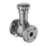
Guía de instalación del muestreador de circuito cerrado: desde la conexión en el esquema P&ID hasta la inspección final de puesta en marcha
Un diseño adecuado muestreador de circuito cerrado proporciona una muestra representativa del proceso al analizador sin volumen muerto, arrastre de gas ni tramos muertos. Sin embargo, incluso un sistema bien diseñado generará datos erróneos si se instala de forma incorrecta. Esta guía explica paso a paso la instalación in situ de un conjunto de muestreador de circuito cerrado: dónde montar el muestreador, cómo conectarlo a la línea de proceso, qué servicios auxiliares necesita, qué pruebas hay que realizar antes de ponerlo en funcionamiento y qué pasos de puesta en servicio garantizan que la muestra sea representativa desde el primer día. La secuencia que se describe a continuación es la misma que nuestro equipo de puesta en servicio ha utilizado en proyectos de Lukoil, BASF y Sinopec, y es aplicable tanto a una cabina de análisis de un solo bucle como a un sistema de muestreo de refinería de múltiples flujos.
Antes de instalar cualquier cosa: 5 comprobaciones para verificar que el lugar está listo
La mayoría de los problemas de instalación por los que nos vuelven a llamar para solucionarlos no son errores de montaje, sino errores relacionados con la preparación del lugar de instalación. Comprueba estos cinco puntos antes de que el muestreador llegue al lugar de instalación.
- Se puede acceder a la ubicación de la toma de proceso. La toma de muestra debe situarse en el lateral de la tubería, no en la parte superior ni en la inferior, y en un tramo recto situado al menos a una distancia equivalente a 5 diámetros de la tubería aguas abajo de cualquier accesorio. Si la toma se encuentra en un «weldolet» que no esté soldado a ras y rectificado, la sonda no sellará correctamente.
- Se ha instalado el sistema de refrigeración y trazado térmico. Los muestreadores de circuito cerrado que manipulan crudo, aceites pesados o cualquier flujo con un punto de fluidez elevado necesitan un suministro de agua de refrigeración a una temperatura de entre 25 y 30 °C y una presión de entre 2 y 3 bar, con una válvula mezcladora termostática. Compruebe que el colector de retorno del agua de refrigeración esté conectado a la torre de refrigeración o a la unidad de refrigeración, y que las válvulas de aislamiento locales estén instaladas y etiquetadas.
- Se ha tendido el conducto para la alimentación eléctrica y las señales. 24 VCC para el solenoide del muestreador, señal de retorno de 4-20 mA para el indicador y un cable específico para el interruptor de proximidad del portacilindros de muestreo. Todas las entradas de los conductos deben estar orientadas hacia abajo o hacia los lados para evitar la entrada de agua, y todas las cajas de conexiones deben contar con tapones de drenaje instalados.
- La superficie de montaje está nivelada y tiene una capacidad de carga específica. Un conjunto de muestreo completamente equipado, con cilindro de muestreo, regulador y tubos, pesa entre 35 y 60 kg. El bastidor de montaje o el bastidor Unistrut debe soldarse a placas de anclaje que estén fijadas a la estructura de acero, y no a la barandilla ni a la bandeja portacables. Consulte con el equipo de ingeniería estructural si el bastidor se va a instalar en un entresuelo nuevo.
- Las tuberías de ventilación y desagüe se conducen a un lugar seguro. El muestreador cuenta con un desagüe en el punto más bajo para el vertido de la muestra y una toma de ventilación en el punto más alto para la purga de aire. Ambos deben conectarse mediante tuberías a un punto de recogida seguro (desagüe cerrado, toma de ventilación a la atmósfera o colector de quema) —nunca al suelo, nunca al nivel del terreno—.
Paso 1: Montar el conjunto del muestreador
La altura de montaje es un pequeño detalle que se amortiza a lo largo de los próximos 20 años. La altura adecuada es la que se encuentra a la altura de los ojos del operario, normalmente Entre 1,4 y 1,6 m por encima de la superficie de paso. De este modo, el punto de intercambio del cilindro de muestreo, el mando del regulador y el manómetro indicador quedan situados en una posición que permite al técnico leerlos, ajustarlos y sustituir el cilindro sin necesidad de utilizar una escalera de mano ni agacharse. No instale el muestreador a más de 1,8 m de altura, ya que dificulta la extracción del cilindro y aumenta el riesgo de que se caiga un cilindro caliente o frío sobre la cubierta.
Herrajes y fijaciones
Utilice tornillería de acero inoxidable 316L para cualquier muestreador instalado en un entorno corrosivo o en alta mar. Para su uso en refinerías en tierra, es aceptable la norma ASTM A193 B7 con sellador de roscas de PTFE. Para servicio con gases ácidos (H₂S > 50 ppm), especifique desde el principio tornillería conforme a la norma NACE MR0175; la adaptación posterior resulta costosa. Los valores de par de apriete deben seguir los datos publicados por el fabricante de los pernos, normalmente entre el 60 % y el 70 % del límite elástico del perno para el tamaño que tenga. Utilice una llave dinamométrica calibrada, no un atornillador de impacto.
Selección de anclas
En hormigón, utiliza anclajes químicos (epoxi o viniléster), no anclajes de expansión: la vibración procedente del recinto del analizador y los ciclos térmicos de la corriente de muestra aflojarán los anclajes de expansión en un plazo de 2 a 3 años. En acero, utiliza soldadura directa para fijar las placas, no pernos pasantes en el pasamanos.
Paso 2: Conectar la línea de proceso
La conexión al proceso es la parte más propensa a errores de instalación. La toma de muestras ya está instalada en la tubería (lo has comprobado durante la preparación de la obra), por lo que el trabajo que hay que realizar aquí consiste en tender la tubería desde la toma hasta la entrada del muestreador.
Dimensionamiento y trazado de los tubos
Utilice tubos de acero inoxidable 316L electropulidos, con un diámetro exterior de 3/8″ y un espesor de pared de 0,049″, para el tramo de conexión al proceso. Cualquier tamaño inferior (1/4″ de diámetro exterior) provoca una caída de presión excesiva y es propenso a obstruirse. Cualquier tamaño superior (1/2″ de diámetro exterior) aumenta el volumen de muestra en la línea y empeora el tiempo de retardo. El recorrido del tubo debe ser el más corto posible, con no más de dos codos de 90 grados, y debe tener una pendiente continua hacia abajo desde la toma hasta el muestreador (o hacia arriba, con un punto de purga en el punto más alto, si el muestreador se encuentra por debajo de la toma).
Realizar una prueba hidrostática de la conexión
Antes de conectar el extremo del muestreador, somete a prueba hidrostática la toma de proceso y el tramo de tubería a 1,5 veces la presión de diseño, mantén la presión durante 30 minutos y revisa toda la longitud en busca de fugas. La toma de muestra es una vía potencial de fuga que resulta difícil de detectar una vez instalado el aislamiento. Una vez superada la prueba, conecte la entrada del muestreador y vuelva a realizar la prueba únicamente en el racor de entrada del muestreador.
Paso 3: Conectar los servicios públicos
Un muestreador de circuito cerrado necesita tres servicios: aire para instrumentos, vapor o sistema eléctrico de trazado térmico y alimentación de 24 VCC. Conéctalos en este orden para poder comprobar cada uno de ellos por separado.
- Aire para instrumentos para el actuador neumático de la válvula de retorno de bucle rápido. Presión de alimentación: 4-6 barg; punto de rocío: -40 °C; sin aceite. Conéctelo al colector de aire mediante una unidad de filtro-regulador-lubricador (FRL) y compruebe que la presión de salida del regulador esté ajustada al valor de diseño (normalmente 4,0 barg).
- Cableado calefactor en el tramo de tubería del proceso. Calefacción por vapor para servicio a alta temperatura; calefacción eléctrica para servicio a baja temperatura. Comprueba que el sistema de calefacción funcione correctamente y que la temperatura de la superficie de la tubería se estabilice en el valor de diseño (normalmente entre 50 y 80 °C para el servicio con crudo) antes de introducir la muestra de proceso.
- Alimentación de 24 VCC a la caja de conexiones del muestreador. Utilice un circuito específico de la distribución de corriente continua del armario del analizador, no una derivación de otro instrumento. Compruebe la polaridad y asegúrese de que la toma de tierra de campo esté conectada al cuerpo del muestreador, no a la estructura de acero.
Paso 4: Instalar el cilindro de muestra y el conector rápido
Una vez comprobados los sistemas de suministro, instale el soporte del cilindro de muestra. El cilindro en sí (normalmente de 300-500 ml, de acero inoxidable 316L y con ambos extremos abiertos) tiene una presión nominal de 1800 psig y está certificado según las normas DOT 3A o EN 10297. Los racores de conexión rápida (normalmente Swagelok QC4 o Festo CK-1/4) deben estar limpios, secos y tapados hasta el momento de la conexión.
Comprueba que no haya fugas en la conexión del cilindro
Una vez colocado el cilindro, presurice la cámara del muestreador con aire de instrumento hasta 2 barg, compruebe la estanqueidad de todos los racores con jabón y mantenga la presión durante 10 minutos. Cualquier fuga es una fuga. No continúe hasta que el sistema sea estanco a las burbujas.
Paso 5: Inspección de puesta en servicio
La puesta en marcha es la última etapa antes de que la muestra pueda llegar al analizador. Realiza la comprobación de funcionamiento siguiendo este orden.
5.1 Realizar una prueba de estanqueidad del muestreador montado
Presurice todo el conjunto del muestreador (lado del proceso + lado de servicios) a 1,1 veces la presión de funcionamiento, mantenga la presión durante 30 minutos, revise todo el conjunto con un detector de fugas o una solución jabonosa y documente el resultado. Cualquier fuga detectada en este momento se incluirá en la lista de tareas pendientes, y no se tratará como algo que “se arreglará en la próxima parada técnica”.
5.2 Purgado y llenado
Conecta un suministro de nitrógeno a la conexión de purga, abre la válvula de purga y purga todo el circuito de muestreo con 3-5 cambios de volumen de nitrógeno. A continuación, cierra la válvula de purga, abre lentamente la válvula principal del proceso y deja que el circuito se llene con la muestra del proceso. Los primeros 3-5 volúmenes de cilindro deben purgarse a un desagüe cerrado, no al analizador; este es el paso de “muestreo de la muestra” que elimina el volumen muerto del sistema.
5.3 Comprobar el caudal del bucle rápido
El circuito rápido es lo que garantiza que la muestra sea representativa. Abre la válvula de retorno del circuito rápido, ajusta el regulador de entrada a la presión de diseño y mide el caudal en el rotámetro o en el caudalímetro másico del retorno. El valor de diseño suele ser de 1-2 l/min para el servicio de gas y de 5-10 l/min para el servicio de líquido. Si el caudal medido es inferior al 80% del valor de diseño, la línea está obstruida; compruebe el filtro de entrada.
5.4 Comprobar la corriente lateral del analizador
Abre la válvula de aguja de la toma del analizador, ajusta el caudal del analizador al valor nominal (normalmente entre 100 y 200 cc/min) y comprueba que el analizador indique el valor esperado para la muestra (por ejemplo, que el medidor de contenido de agua indique el contenido de agua conocido y que el medidor de conductividad indique la conductividad conocida). Si la lectura no es correcta, el acondicionamiento de la muestra es incorrecto: vuelve al paso 5.2 y vuelve a llenar la muestra.
5.5 Aprobación
Anota los datos de puesta en servicio en la hoja de puesta en servicio estándar: resultados de la prueba de fugas, valores de caudal, lecturas de presión, lectura del analizador frente a la prevista, número de serie del cilindro de muestra y el nombre del operario que presenció la revisión final. La hoja firmada es lo que el equipo de operaciones recibe de tu equipo de puesta en servicio.
6 errores habituales en la instalación
| Error | Síntoma | Corregir |
|---|---|---|
| Toca la parte superior del tubo horizontal | La muestra es gaseosa, no líquida. | Vuelve a roscar el lateral de la tubería, al menos a 5D aguas abajo de cualquier accesorio. |
| No hay pendiente continua en el tramo de tubería | La muestra tiene un retraso de entre 20 y 30 minutos; hay zonas en las que la muestra está obsoleta | Redirigir la tubería con una pendiente continua y añadir un desagüe intermedio |
| Instalado a una altura excesiva (>1,8 m) | Riesgo de caída del cilindro; el operario no lo utiliza correctamente | Vuelve a instalarlo a una altura de entre 1,4 y 1,6 m, o instala una plataforma fija con barandilla. |
| No se ha comprobado el sistema de calefacción antes de introducir la muestra | La muestra se enfría, la cera se separa y se obstruyen los conductos. | Mantén el sistema de trazado térmico en funcionamiento durante 24 horas antes de introducir la muestra. |
| Muestreador en una carcasa no clasificada en una zona peligrosa | Fuente de ignición, infracción del código | Reubicación en una caja «Ex d» homologada para el grupo de gases y la clase T |
| Volumen del primer llenado enviado al analizador | El volumen muerto del analizador provoca lecturas erróneas durante las primeras 1-2 horas | Dirige los primeros volúmenes de 3 a 5 cilindros hacia el desagüe cerrado |
Cómo se relaciona esto con el resto del sistema
El muestreador de circuito cerrado Es la parte frontal del sistema de muestreo del analizador. Las decisiones de diseño que se tomen en el momento de la instalación afectan directamente a la calidad de los datos del analizador. Un muestreador montado a una altura incorrecta, conectado a una toma mal situada o que funcione con un bucle rápido defectuoso producirá una lectura del analizador que se desvíe, se retrase o, sencillamente, sea errónea. Para profundizar en las decisiones de diseño que han llevado a esta instalación, consulte nuestro Guía de diseño de sistemas de muestreo. Para conocer los componentes específicos que se montan en el cuerpo del muestreador —conectores rápidos, válvulas de aguja y racores para tubos—, consulte nuestro Categoría de accesorios de muestreo.
Si necesitas ayuda con tu instalación concreta —revisión del diseño, selección de componentes o puesta en marcha in situ—, ponte en contacto con nuestro equipo de ingeniería. Hemos instalado muestreadores de circuito cerrado en refinerías, plantas petroquímicas y plataformas marinas en toda la UE, Norteamérica, Oriente Medio y Asia, y podemos ofrecerte apoyo para tu proyecto, desde los esquemas P&ID hasta la inspección in situ.
 English
 Russian
 Arabic
 Spanish
 Portuguese
 Chinese