






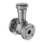
Emergency Relief Valve Sizing: A Step-by-Step Technical Guide for Storage Tanks
An undersized صمام تنفيس الطوارئ is one of the few piece of process equipment that will fail catastrophically without any warning. If a storage tank’s emergency venting capacity is smaller than the thermal or fire heat input during an emergency, the tank will over-pressurize, the shell will buckle, and the consequences range from a spill to a BLEVE. This guide walks through the complete emergency relief valve sizing procedure for atmospheric and low-pressure storage tanks, based on API 2000 (7th edition), API 520/521, ، و ISO 23251.
What Is an Emergency Relief Valve and When Does It Activate?
A pressure vacuum relief valve (PVRV) handles normal in-breathing and out-breathing. An emergency relief valve (ERV) is a separate, larger vent device that activates only during abnormal events where the normal vent is overwhelmed. The three primary scenarios that require emergency venting are:
- Fire exposure — liquid in the tank absorbs heat from a pool fire or exposure fire, vaporizes, and the vapor must be discharged faster than the PVRV can handle
- Blocked outlet — a pump cavitation event, a closed isolation valve, or a thermal expansion scenario that pushes liquid into the vapor space at high flow rate
- Runaway reaction or utility failure — applies mainly to jacketed vessels and chemical storage; less common in crude or product tankage
API 2000 defines three tiers of analysis: Tier 1 (conservative, no wetted area credit), Tier 2 (intermediate, partial wetted area), and Tier 3 (rigorous, full consequence modeling). For most fixed-roof atmospheric tanks, Tier 1 or Tier 2 is sufficient and auditable.
Step 1 — Determine the Design Scenario
Fire Case vs. Non-Fire Case
The dominant sizing scenario for almost all atmospheric storage tanks is the fire case. API 2000 Table B.1 gives the heat absorption equation for tanks with wetted surface area below and above 260 m²:
- Wetted surface ≤ 260 m²: Q = 43,200 × F × A0.82 (metric, kJ/h)
- Wetted surface > 260 m²: Q = 70,900 × F × A0.5 (metric, kJ/h)
Where F is the environmental factor (1.0 for bare metal tanks, 0.3 for tanks with approved insulation meeting API criteria, 0.15 for water-spray systems) and A is the wetted surface area in m².
Calculating Wetted Surface Area
Wetted surface area is the tank surface that can be in contact with liquid during a fire. For a vertical cylindrical tank, the convention under API 2000 is the lower 9.1 m (30 ft) of shell height, plus the bottom. For floating roof tanks with the roof in the down position, include the roof area. For horizontal tanks, the full shell up to 9.1 m is wetted.
Step 2 — Calculate Required Vapor Relief Rate
Once you have the fire heat input Q (kJ/h), convert to the required vapor flow using the latent heat of vaporization of the stored product:
W = Q / Hv
Where W is the required mass flow rate (kg/h) and Hv is the latent heat of vaporization at the relieving conditions (kJ/kg). For common petroleum products:
| Product | Latent Heat Hv (kJ/kg at 38°C) | Typical Relieving Temp (°C) |
|---|---|---|
| Gasoline (90 RON) | 310–340 | 60–80 |
| Naphtha | 290–320 | 55–75 |
| Crude oil (light) | 230–270 | 80–110 |
| Diesel (gas oil) | 220–250 | 100–130 |
| Jet fuel (A-1) | 300–330 | 70–90 |
| Ethanol | 855–900 | 78–85 |
If the latent heat is unknown, use the most conservative (lowest) value for the product family. Underestimating Hv increases the calculated vapor flow W and leads to a larger, safer valve selection.
Step 3 — Convert Mass Flow to Volumetric Flow at Relieving Conditions
Emergency relief valve capacity is typically rated in Nm³/h (normal cubic meters per hour) or SCFH (standard cubic feet per hour). To convert the mass flow W to volumetric flow at standard conditions:
Qstd = W × R × Tstd / (Pstd × M)
Where R is the gas constant (8,314 J/kmol·K), Tstd is 273.15 K (0°C standard), Pstd is 101,325 Pa, and M is the vapor molecular weight. For a petroleum product, M can be estimated from the ASTM D86 distillation curve or API gravity correlation.
Example Calculation: 2,000 m³ Crude Oil Tank
Tank shell diameter: 16 m, liquid height: 10 m (full), insulation: none (F = 1.0)
- Wetted area: π × 16 m × 9.1 m + π/4 × 16² = 457 + 201 = 658 m² (above 260 m²)
- Heat input: Q = 70,900 × 1.0 × 6580.5 = 70,900 × 25.65 = 1,818,000 kJ/h
- Latent heat (light crude, 250 kJ/kg): W = 1,818,000 / 250 = 7,272 kg/h
- Molecular weight (light crude, M ≈ 85): Qstd = 7,272 × 8,314 × 273 / (101,325 × 85) ≈ 2,150 Nm³/h
The emergency vent device must pass at least 2,150 Nm³/h at the tank design pressure (typically 17–35 mbar for atmospheric tanks).
Step 4 — Apply Environmental and Drainage Credit
API 2000 allows a reduction in required relief capacity when the site has grading and drainage that prevents pooled liquid from accumulating within 30 m of the tank. This is the drainage credit: if drainage is adequate, the heat input formula uses a 0.5 F factor instead of the default 1.0. Many older tank farms do not qualify because drainage channels are shared or blocked.
Step 5 — Select the Emergency Relief Valve
Emergency Vent Valve vs. Gauge Hatch Vent vs. Weak Seam Roof
| Device Type | Activation Pressure | Re-seals After Event | Suitable For |
|---|---|---|---|
| Emergency relief valve (spring-loaded) | Adjustable (e.g. 25–85 mbar) | Yes | All atmospheric tanks, preferred option |
| Weight-loaded emergency vent | Fixed by weight | Yes | Simpler designs, lower cost |
| Gauge hatch relief port | Very low (<5 mbar) | No (open until reset) | Secondary/last resort only |
| Weak seam roof joint | Structural failure load | No (tank damage) | Final over-pressure protection, not a sized device |
Certified Capacity Data
All emergency relief valves must carry a certified flow capacity curve from the manufacturer, tested in accordance with API 2000 Annex D or ISO 28300. The certificate lists capacity in Nm³/h at a range of set pressures. Select a valve or a bank of valves whose combined certified capacity exceeds the calculated W at the design set pressure. Include a 10–25% margin above the calculated requirement to account for future capacity additions or product changes.
Step 6 — Verify Inlet and Outlet Piping
Emergency relief valves on storage tanks are almost always top-mounted (on a nozzle at the tank roof), but the inlet nozzle size and outlet piping are critical:
- Inlet nozzle: sized so pressure drop across the inlet is less than 3% of set pressure at full flow. For a 17 mbar set valve, inlet drop must be below 0.5 mbar at rated flow.
- Outlet piping: for valves with vapor collection headers, back-pressure must stay below 10% of set pressure for conventional valves, or below 50% for balanced bellows designs.
- No liquid traps: the outlet piping must drain back to the tank. Any liquid trap will reduce effective vent area and can seal the valve closed during an emergency.
Step 7 — Documentation and Inspection Requirements
Every sized and installed emergency relief valve should carry a Valve Data Sheet showing: tag number, tank ID, set pressure, certified capacity at set, design scenario, product latent heat used, and environmental factor applied. Inspection requirements under API 653 call for functional testing every 5 years for atmospheric storage tanks, or more frequently if product is corrosive. Weight-loaded valves require seating surface inspection; spring-loaded valves require spring tension verification.
Common Emergency Relief Valve Sizing Errors
- Using PVRV flow coefficients for ERV sizing — ERV valves have different Cd values; always use the ERV’s own certified capacity curve
- Neglecting vapor superheat — at high fire heat input, the relieving vapor may be significantly above the boiling point, reducing density and increasing volumetric flow
- Applying insulation credit without verifying API compliance — insulation must meet API 2000 Annex C criteria (coke-proof, drain-proof, fireproof for 2 hours); standard mineral wool blankets do not qualify automatically
- Single-valve design for tanks with multiple products — if a tank swings between products with different latent heats, size for the lightest product (lowest Hv)
- Forgetting parallel operating valves share capacity — the capacity of multiple ERVs installed in parallel is additive only if all valves have the same set pressure; staggered settings reduce effective combined capacity
Integration With Wanan Emergency Relief Valves
Wanan Technology’s صمامات التنفيس في حالات الطوارئ are manufactured to API 2000 / ISO 28300 and are available with third-party capacity certification from SGS or TÜV. For tank farm projects requiring sizing support and certified valve data sheets, contact our engineering team with the stored product MSDS, tank diameter, maximum operating liquid level, and site drainage classification. We provide sizing calculations, valve selection, and all documentation required for HAZOP and regulatory submission.
For related sizing methodology, see our How Does a PVRV Work guide covering normal venting under API 2000, and our API 2000 Tank Vent Sizing walkthrough for thermal in-breathing and out-breathing calculations.
FAQ: Emergency Relief Valve Sizing
Q: Can I use a pressure safety valve (PSV) rated to ASME Section VIII instead of an API 2000 emergency relief valve?
A: Not directly. ASME PSVs are designed for pressure vessels, not atmospheric storage tanks. Their set pressures start at around 100 mbar, which is far above the operating pressure of an atmospheric tank. Using an ASME PSV on a cone-roof tank would mean the tank overpressurizes to near structural failure before the valve opens. API 2000 / ISO 28300 valves are designed for set pressures as low as 2–5 mbar, appropriate for atmospheric storage.
Q: How do I verify that a vendor’s emergency relief valve meets the required capacity?
A: Request the capacity certification test report — not just the catalog curve. Certified ERV capacity is measured on a flow test rig at the valve’s set pressure, with the actual valve size and trim. Third-party certification from SGS, TÜV, or DEKRA is the highest confidence level. API 2000 Annex D describes the test procedure; valves certified per this annex can be used in API 2000 sizing calculations directly.
Q: What is the difference between emergency relief capacity and normal venting capacity?
A: Normal venting covers thermal breathing and liquid movement — typically tens to hundreds of Nm³/h for most tanks. Emergency fire-case venting for the same tank can be 10–100× larger. A 5,000 m³ crude oil tank might need 500 Nm³/h of normal vent capacity but 8,000–15,000 Nm³/h of emergency vent capacity during a fire exposure scenario.
Q: Does a floating roof tank need an emergency relief valve?
A: Generally, no — the floating roof itself rises and exposes the rim seal as an emergency vent when the roof reaches maximum travel. However, if the roof is in the down position (empty tank, maintenance), an emergency vent is required. Many sites install a permanent ERV on the center vent to cover all scenarios.
Q: How often should emergency relief valves be function-tested?
A: API 653 recommends functional testing every 5 years for atmospheric tank ERVs. Weight-loaded valves should have seat lapping checked; spring-loaded valves should have set pressure verified on a test stand. In corrosive or high-sulfur crude service, shorten the inspection interval to 2–3 years, as sulfur compounds attack seat sealing surfaces and can cause valves to stick open or closed.
Q: Can I install an emergency relief valve on a cone-roof tank without a flame arrester?
A: For most products it is not required, but for products with flash points below 60°C (Class I and II flammable liquids), an in-line deflagration arrestor between the vent and the outlet is strongly recommended. API 2000 does not mandate it, but NFPA 30 and local regulatory codes in EU, UK, and the Middle East commonly require it. Check local regulations before deciding.
 English
 Russian
 Arabic
 Spanish
 Portuguese
 Chinese